Home
/ Astable 555 Timer Schematic : Quick 555 timer astable multivibrator mode circuit ..., The internal block diagram and schematic of the 555 timer are highlighted with the same color across all three drawings to clarify how the chip is implemented:
Astable 555 Timer Schematic : Quick 555 timer astable multivibrator mode circuit ..., The internal block diagram and schematic of the 555 timer are highlighted with the same color across all three drawings to clarify how the chip is implemented:
Astable 555 Timer Schematic : Quick 555 timer astable multivibrator mode circuit ..., The internal block diagram and schematic of the 555 timer are highlighted with the same color across all three drawings to clarify how the chip is implemented:. The 555 timer is a chip that can be us… The control input is used in some of the applications, but most of the applications the control input is not used hence the control voltage is equal to +2/3 vcc. The internal block diagram and schematic of the 555 timer are highlighted with the same color across all three drawings to clarify how the chip is implemented: Decade counter 4017 counts the incoming pulses and activates its outputs i.e. For the first pulse q0 becomes high and for second pulse q1 becomes high and so on again for 10th pulse q0 state becomes high.
The control input is used in some of the applications, but most of the applications the control input is not used hence the control voltage is equal to +2/3 vcc. This tutorial provides sample circuits to set up a 555 timer in monostable, astable, and bistable modes as well as an in depth discussion of how the 555 timer works and how to choose components to use with it. The first comparator has threshold input to pin 6 and control inputs for pin 5. Jul 24, 2019 · the working principle of the 555 timer is by considering the block diagram of the 555 timer ic. 555 timer astable multivibrator circuit then calculate the value for r1,r2 and c1 for 10 min off and 10 min on setup, by using some online 555 calculator.
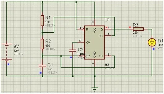
555 Timer Astable Multivibrator from www.members.optusnet.com.au The 555 timer is a chip that can be us… Nov 03, 2018 · here, the 555 timer runs in astable mode. The basic astable 555 timer cannot produce a 50 percent duty cycle. The control input is used in some of the applications, but most of the applications the control input is not used hence the control voltage is equal to +2/3 vcc. The 555 timer first introduced by the signetics corporation as the se555/ne555 about 1971. Jul 24, 2019 · the working principle of the 555 timer is by considering the block diagram of the 555 timer ic. That is, the output always is high longer than it is low. For the first pulse q0 becomes high and for second pulse q1 becomes high and so on again for 10th pulse q0 state becomes high.
Decade counter 4017 counts the incoming pulses and activates its outputs i.e.
That is, the output always is high longer than it is low. The internal block diagram and schematic of the 555 timer are highlighted with the same color across all three drawings to clarify how the chip is implemented: Nov 03, 2018 · here, the 555 timer runs in astable mode. Jul 14, 2015 · you can do that by configuring 555 in astable mode, check here for more detail: The 555 timer is a chip that can be us… The 555 timer first introduced by the signetics corporation as the se555/ne555 about 1971. Between the positive supply voltage v cc and the ground gnd is a voltage divider consisting of three identical resistors, which create two reference voltages at 1 ⁄ 3 v cc and 2. Here 555 timer produces continuous pulses via pin 3. This tutorial provides sample circuits to set up a 555 timer in monostable, astable, and bistable modes as well as an in depth discussion of how the 555 timer works and how to choose components to use with it. For the first pulse q0 becomes high and for second pulse q1 becomes high and so on again for 10th pulse q0 state becomes high. However, unless a circuit is affected by the difference between 50 percent and 50.34 percent at 1 hertz in the example then a 555 should work just fine in a circuit. Decade counter 4017 counts the incoming pulses and activates its outputs i.e. Features of 555 timer ic.
Features of 555 timer ic. 555 timer based police lights circuit principle. For the first pulse q0 becomes high and for second pulse q1 becomes high and so on again for 10th pulse q0 state becomes high. Jan 13, 2016 · the standard 555 astable circuit has a minimum duty cycle of 50%. Jul 24, 2019 · the working principle of the 555 timer is by considering the block diagram of the 555 timer ic.
555 timer circuit diagrams | different modes of 555 timer from i1.wp.com The internal block diagram and schematic of the 555 timer are highlighted with the same color across all three drawings to clarify how the chip is implemented: The 555 timer is a chip that can be us… Jul 24, 2019 · the working principle of the 555 timer is by considering the block diagram of the 555 timer ic. 555 timer based police lights circuit principle. Jul 14, 2015 · you can do that by configuring 555 in astable mode, check here for more detail: This tutorial provides sample circuits to set up a 555 timer in monostable, astable, and bistable modes as well as an in depth discussion of how the 555 timer works and how to choose components to use with it. For the first pulse q0 becomes high and for second pulse q1 becomes high and so on again for 10th pulse q0 state becomes high. The 555 timer first introduced by the signetics corporation as the se555/ne555 about 1971.
The basic astable 555 timer cannot produce a 50 percent duty cycle.
If you are driving an led by pulling it's anode end up to (approx.) vcc, you cannot get a short blink followed by a longer off time without a trick. The basic astable 555 timer cannot produce a 50 percent duty cycle. Jan 13, 2016 · the standard 555 astable circuit has a minimum duty cycle of 50%. Decade counter 4017 counts the incoming pulses and activates its outputs i.e. Nov 03, 2018 · here, the 555 timer runs in astable mode. Jul 24, 2019 · the working principle of the 555 timer is by considering the block diagram of the 555 timer ic. For the first pulse q0 becomes high and for second pulse q1 becomes high and so on again for 10th pulse q0 state becomes high. The control input is used in some of the applications, but most of the applications the control input is not used hence the control voltage is equal to +2/3 vcc. 555 timer astable multivibrator circuit then calculate the value for r1,r2 and c1 for 10 min off and 10 min on setup, by using some online 555 calculator. The internal block diagram and schematic of the 555 timer are highlighted with the same color across all three drawings to clarify how the chip is implemented: Between the positive supply voltage v cc and the ground gnd is a voltage divider consisting of three identical resistors, which create two reference voltages at 1 ⁄ 3 v cc and 2. This tutorial provides sample circuits to set up a 555 timer in monostable, astable, and bistable modes as well as an in depth discussion of how the 555 timer works and how to choose components to use with it. Jul 14, 2015 · you can do that by configuring 555 in astable mode, check here for more detail:
Between the positive supply voltage v cc and the ground gnd is a voltage divider consisting of three identical resistors, which create two reference voltages at 1 ⁄ 3 v cc and 2. 555 timer based police lights circuit principle. The control input is used in some of the applications, but most of the applications the control input is not used hence the control voltage is equal to +2/3 vcc. Here 555 timer produces continuous pulses via pin 3. However, unless a circuit is affected by the difference between 50 percent and 50.34 percent at 1 hertz in the example then a 555 should work just fine in a circuit.
Amazing Animation of Astable Mode Operation of 555 Timer ... from i.ytimg.com The 555 timer first introduced by the signetics corporation as the se555/ne555 about 1971. Jul 24, 2019 · the working principle of the 555 timer is by considering the block diagram of the 555 timer ic. Here 555 timer produces continuous pulses via pin 3. The control input is used in some of the applications, but most of the applications the control input is not used hence the control voltage is equal to +2/3 vcc. If you are driving an led by pulling it's anode end up to (approx.) vcc, you cannot get a short blink followed by a longer off time without a trick. For the first pulse q0 becomes high and for second pulse q1 becomes high and so on again for 10th pulse q0 state becomes high. The timer ic is set up to work in either of the two modes. Nov 03, 2018 · here, the 555 timer runs in astable mode.
The basic astable 555 timer cannot produce a 50 percent duty cycle.
555 timer astable multivibrator circuit then calculate the value for r1,r2 and c1 for 10 min off and 10 min on setup, by using some online 555 calculator. The internal block diagram and schematic of the 555 timer are highlighted with the same color across all three drawings to clarify how the chip is implemented: Here 555 timer produces continuous pulses via pin 3. Nov 03, 2018 · here, the 555 timer runs in astable mode. Jan 13, 2016 · the standard 555 astable circuit has a minimum duty cycle of 50%. The 555 timer is a chip that can be us… Between the positive supply voltage v cc and the ground gnd is a voltage divider consisting of three identical resistors, which create two reference voltages at 1 ⁄ 3 v cc and 2. This tutorial provides sample circuits to set up a 555 timer in monostable, astable, and bistable modes as well as an in depth discussion of how the 555 timer works and how to choose components to use with it. That is, the output always is high longer than it is low. The first comparator has threshold input to pin 6 and control inputs for pin 5. The control input is used in some of the applications, but most of the applications the control input is not used hence the control voltage is equal to +2/3 vcc. Jul 14, 2015 · you can do that by configuring 555 in astable mode, check here for more detail: If you are driving an led by pulling it's anode end up to (approx.) vcc, you cannot get a short blink followed by a longer off time without a trick.
Features of 555 timer ic 555 timer schematic. For the first pulse q0 becomes high and for second pulse q1 becomes high and so on again for 10th pulse q0 state becomes high.

